Custom Modulation/OFDM
These Carrier settings are applicable when you select Custom OFDM in the Waveform > Basic tab.
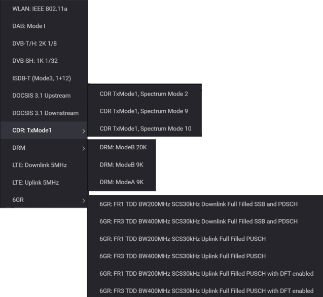
Use the Quick Setups drop-down menu to select a quick setup from several supported formats shown below. Quick setups enable you to configure complex signals for signal generation, equivalent to 89600B VSA setups in signal analysis.
|
SCPI Command |
[:SOURce]:RADio:CMODulation:WAVeform[:ARB]:OFDM:SETup WLAN_802_11A|DAB_MODE_I|DVB_T_H_2K_1_8|DVB_SH_1K_1_32|ISDB_T_MODE3_1_12|DOCSIS_3_1_US|DOCSIS_3_1_DS|LTE_DL_5MHZ|LTE_UL_5MHZ|CDR_TXMODE1_SM2|CDR_TXMODE1_SM9|CDR_TXMODE1_SM10|DRM_MODEB_20K|DRM_MODEB_9K|DRM_MODEA_9K|R6G_FR1_DL_200_30_SSB_PDSCH|R6G_FR3_DL_400_30_SSB_PDSCH|R6G_FR1_UL_200_30_PUSCH|R6G_FR3_UL_400_30_PUSCH|R6G_FR1_UL_200_30_PUSCH_DFT|R6G_FR3_UL_400_30_PUSCH_DFT |
|
SCPI Example |
|
|
Couplings |
|
|
Preset |
|
|
State Saved |
Yes |
|
Initial S/W Revision |
A.20.01 |
This feature saves the Custom Modulation configuration as a 89600B VSA setup file, simplifying VSA configuration so you can quickly demodulate the signal.
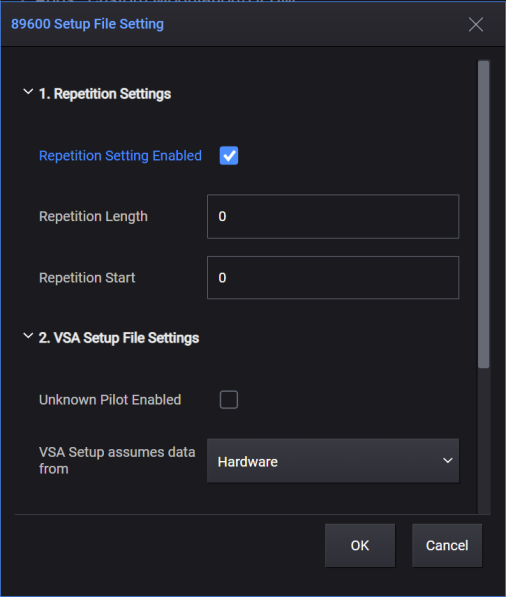
The 89600B VSA uses a parameter called Resource Repeat Index to reduce the length of the Resource Map and Resource Modulation arrays. The PathWave Signal Generation for Custom Modulation/OFDM software, however, uses Repetition Start and Repetition Length to indicate the periodicity (how many symbols are repeated) between OFDM symbols. Therefore, clicking the Save to 89600 VSA Setup button opens the following dialog, to allow you to adjust these values before saving the setup file.
To support the "Frame Definition" parameters in 89600 VSA Custom OFDM Demod Properties, the Name of Resource Block should be configured as below:
The part in square brackets "[]_" of the Name will be mapped to the Frame Part and Allocation name of VSA. For example, "[FP1]_Alloc1" maps to VSA's Frame Part "FP1" and Allocation "Alloc1".
All Resource Blocks with Name that does NOT have the "[]_" identifier will be put into one VSA Frame Part with default name "FramePart0".
The following section describes various settings available in the 89600 Setup file Setting dialog.
Choices: On | Off
Default: Off
Enable or disable the repetition setting for the setx file to be exported.
If symbol mapping has repeatability, select On to set Repetition Start and Repetition Length to reduce the VSA setup file size. Otherwise, it should be set to Off.
Range: 0 to Number of OFDM Symbols
Default: 0
Set the repetition length (in symbols) when generating the 89600 setup file. This parameter indicates the periodicity of the resource setting. Set to zero if there is no periodicity. Only some of the basic OFDM parameters are saved to the 89600B setup file. You may need to adjust other parameters in the 89600B VSA to achieve optimum demodulation results.
Range: 0 to Number of OFDM Symbols
Default: 0
Set the repetition start (in symbols) when generating the 89600 setup file. If the Repetition Length is not zero, this parameter indicates the start symbol index for repetition.
Choices: On | Off
Default: Off
Enable or disable the unknown pilot. If enabled, the pilot resource element will be treated as unknown pilot on the VSA side.
Choices: Hardware | Recording
Default: Hardware
Set the data source in the saved VSA setx file.
Range: 0 to 200 ms
Default: 4 us
Set the idle interval in-between OFDM frames, in seconds. When idle interval is set to zero, a continuous waveform will be generated.
|
SCPI Command |
[:SOURce]:RADio:CMODulation:WAVeform[:ARB]:OFDM:IDle:INTerval <real> [:SOURce]:RADio:CMODulation:WAVeform[:ARB]:OFDM:IDle:INTerval? |
|
SCPI Example |
|
|
Couplings |
|
|
Preset |
4e-06 |
|
State Saved |
Yes |
|
Min |
0 |
|
Max |
200 ms |
|
Initial S/W Revision |
A.20.01 |
Range: 1 kHz to 100 GHz
Default: 20 MHz
Set the system sampling rate, in Hz.
|
SCPI Command |
[:SOURce]:RADio:CMODulation:WAVeform[:ARB]:OFDM:SAMPle:FREQuency <real> [:SOURce]:RADio:CMODulation:WAVeform[:ARB]:OFDM:SAMPle:FREQuency? |
|
SCPI Example |
|
|
Couplings |
|
|
Preset |
20000000 |
|
State Saved |
Yes |
|
Min |
1 kHz |
|
Max |
100 GHz |
|
Initial S/W Revision |
A.20.01 |
Range: 0° to 360°
Default: 0°
Enter the initial phase of the carrier signal, in degrees. A fixed phase rotation will be added to the generated OFDM signal.
You can assign different initial phases to different waveforms for the beamforming test.
|
SCPI Command |
[:SOURce]:RADio:CMODulation:WAVeform[:ARB]:OFDM:IPHase <real> [:SOURce]:RADio:CMODulation:WAVeform[:ARB]:OFDM:IPHase? |
|
SCPI Example |
|
|
Couplings |
|
|
Preset |
0 |
|
State Saved |
Yes |
|
Min |
0° |
|
Max |
360° |
|
Initial S/W Revision |
A.20.01 |
Apply a frequency offset to the generated baseband IQ. The max offset is limited by the current sampling rate. To apply a larger frequency offset, you need to increase the OSR to a proper value.
Max offset = System Sample Frequency * Oversampling Ratio / 2.56 - System Sample Frequency / 2
|
SCPI Command |
[:SOURce]:RADio:CMODulation:WAVeform[:ARB]:OFDM:FREQuency:OFFSet <real> [:SOURce]:RADio:CMODulation:WAVeform[:ARB]:OFDM:FREQuency:OFFSet? |
|
SCPI Example |
|
|
Couplings |
This setting is available only when Multicarrier Enabled is set to OFF. |
|
Preset |
0 |
|
State Saved |
Yes |
|
Min |
|
|
Max |
|
|
Initial S/W Revision |
A.20.01 |
Range: 4 to 16384
Default: 64
Set the FFT length of the OFDM signal. The input can also be set with non-powers of 2.
If the input FFT length is not divisible by 2, the input value is subtracted by one. For example, an input of 5 will become a valid value of 4.
An input of 6 is also valid for this feature.
|
SCPI Command |
[:SOURce]:RADio:CMODulation:WAVeform[:ARB]:OFDM:FLENgth <integer> [:SOURce]:RADio:CMODulation:WAVeform[:ARB]:OFDM:FLENgth? |
|
SCPI Example |
|
|
Couplings |
|
|
Preset |
64 |
|
State Saved |
Yes |
|
Min |
4 |
|
Max |
16384 |
|
Initial S/W Revision |
A.20.01 |
Click the > button displayed with this setting to open the Cyclic Prefix Length editor for configuring the length of the OFDM symbols within a frame. In this editor,
You can set each symbol individually or use a preset configuration.
You can add or remove cyclic prefix setting rows. Each setting row contains the following:
Symbol Index: Enter "All" for all symbols, or enter a comma-seprated string to indicate the symbol index, for example, "0,3,6" or "0:4" or "0:4:20". This is the same syntax as Symbol Index under Resource Mapping.
CP Length (%): Enter the cyclic prefix length as the percentage of FFT length.
CP Length: Enter the absolute cyclic prefix length by samples before oversampling.
|
SCPI Command |
[:SOURce]:RADio:CMODulation:WAVeform[:ARB]:OFDM:CPLength [:SOURce]:RADio:CMODulation:WAVeform[:ARB]:OFDM:CPLength? |
|
SCPI Example |
|
|
Couplings |
|
|
Preset |
16 |
|
State Saved |
Yes |
|
Initial S/W Revision |
A.20.01 |
Click the > button displayed with this setting to open the Cyclic Suffix Length editor for configuring the length of the OFDM symbols within a frame. In this editor,
You can set each symbol individually or use a preset configuration.
You can add or remove cyclic suffix setting rows. Each setting row contains the following:
Symbol Index: Enter "All" for all symbols, or enter a comma-seprated string to indicate the symbol index, like "0,3,6" or "0:4" or "0:4:20". This is the same syntax as Symbol Index under Resource Mapping.
CS Length (%): Enter the cyclic suffix length as the percentage of FFT length.
CS Length: Enter the absolute cyclic suffix length by samples before oversampling.
|
SCPI Command |
[:SOURce]:RADio:CMODulation:WAVeform[:ARB]:OFDM:CSLength [:SOURce]:RADio:CMODulation:WAVeform[:ARB]:OFDM:CSLength? |
|
SCPI Example |
|
|
Couplings |
|
|
Preset |
0 |
|
State Saved |
Yes |
|
Initial S/W Revision |
A.20.01 |
Range: 0 to FFT Length/2
Default: 6
Set the number of lower guard subcarriers. No data will be transmitted on these subcarriers.
|
SCPI Command |
[:SOURce]:RADio:CMODulation:WAVeform[:ARB]:OFDM:GUARd:LOWer <real> [:SOURce]:RADio:CMODulation:WAVeform[:ARB]:OFDM:GUARd:LOWer? |
|
SCPI Example |
|
|
Couplings |
|
|
Preset |
6 |
|
State Saved |
Yes |
|
Min |
|
|
Max |
|
|
Initial S/W Revision |
A.20.01 |
Range: 0 - (FFT Length - Guard Lower Subcarriers - 1)
Default: 5
Set the number of upper guard subcarriers. No data will be transmitted on these subcarriers.
|
SCPI Command |
[:SOURce]:RADio:CMODulation:WAVeform[:ARB]:OFDM:GUARd:UPPer <real> [:SOURce]:RADio:CMODulation:WAVeform[:ARB]:OFDM:GUARd:UPPer? |
|
SCPI Example |
|
|
Couplings |
|
|
Preset |
5 |
|
State Saved |
Yes |
|
Min |
|
|
Max |
|
|
Initial S/W Revision |
A.20.01 |
Displays the subcarrier spacing (System Sample Frequency / FFT Length).
This value is read-only and automatically updates with changes to FFT Length and System Sample Frequency.
Displays the actual signal bandwidth of the used subcarriers (FFT Length - Guard Lower Subcarriers - Guard Upper Subcarriers).
This value is read-only.
Range: 1 to 2000
Default: 64
Set the number of OFDM symbols in a frame, which usually includes preamble symbols and data symbols.
|
SCPI Command |
[:SOURce]:RADio:CMODulation:WAVeform[:ARB]:OFDM:SYMBols:COUNt <real> [:SOURce]:RADio:CMODulation:WAVeform[:ARB]:OFDM:SYMBols:COUNt? |
|
SCPI Example |
|
|
Couplings |
|
|
Preset |
64 |
|
State Saved |
Yes |
|
Min |
|
|
Max |
|
|
Initial S/W Revision |
A.20.01 |
Choices: First Symbol | Preamble Symbol(s) | All Symbol(s)
Default: First Symbol
In most cases, the power level for an OFDM signal is not constant across all symbols. This parameter allows you to choose which symbols in the waveform will have their power associated with the amplitude displayed on instrument's front panel. Other parts will have a relative power gap to the referenced part based on the rms ratio. Preamble Symbol(s) are the symbols mapped to Preamble in Resource Mapping. If there is no preamble symbol, the first symbol will be used.
|
SCPI Command |
[:SOURce]:RADio:CMODulation:WAVeform[:ARB]:OFDM:POWer:REFerence FSYMbol|PSYMbol|ASYMbol|ABSYMbol [:SOURce]:RADio:CMODulation:WAVeform[:ARB]:OFDM:POWer:REFerence? |
|
SCPI Example |
|
|
Couplings |
|
|
Preset |
FSYMbol |
|
State Saved |
Yes |
|
Initial S/W Revision |
A.20.01 |
Range: 0 to 0.5
Default: 0.005
Set the windowing length used to smooth OFDM symbol transitions.
|
SCPI Command |
[:SOURce]:RADio:CMODulation:WAVeform[:ARB]:OFDM:WBETa <real> [:SOURce]:RADio:CMODulation:WAVeform[:ARB]:OFDM:WBETa? |
|
SCPI Example |
|
|
Couplings |
|
|
Preset |
0.005 |
|
State Saved |
Yes |
|
Min |
|
|
Max |
|
|
Initial S/W Revision |
A.20.01 |
Choices: Centered at Symbol Boundary | Starting at Symbol Boundary
Default: Centered at Symbol Boundary
Select the windowing method applied to the OFDM symbol transitions. The raised cosine window can be centered at the OFDM symbol boundary, or starting from the OFDM symbol boundary as illustrated and described below.
Centered at Symbol Boundary: Specifies that the window is applied with its center at the boundary between two orthogonal frequency division multiplexing (OFDM) symbols.
Starting at Symbol Boundary: Specifies that the window is applied with its starting position at the boundary between two OFDM symbols.
|
SCPI Command |
[:SOURce]:RADio:CMODulation:WAVeform[:ARB]:OFDM:WMEThod CASBoundary|SASBoundary [:SOURce]:RADio:CMODulation:WAVeform[:ARB]:OFDM:WMETHod? |
|
SCPI Example |
|
|
Couplings |
|
|
Preset |
CASBoundary |
|
State Saved |
Yes |
|
Initial S/W Revision |
A.20.01 |
Choices: None | Gaussian | Root Nyquist | Nyquist | Rectangle | User Defined
Default: None
Select the filter type to be applied to the waveform.
|
SCPI Command |
[:SOURce]:RADio:CMODulation:WAVeform[:ARB]:OFDM:FILTer:TYPE NONE|RNYQuist|NYQuist|GAUSsian|RECTangle|UDEFined [:SOURce]:RADio:CMODulation:WAVeform[:ARB]:OFDM:FILTer:TYPE? |
|
SCPI Example |
|
|
Couplings |
|
|
Preset |
NONE |
|
State Saved |
Yes |
|
Initial S/W Revision |
A.20.01 |
Range: 0.1 to 1.0
Default: 0.5
Set the BT product of the Gaussian filter.
|
SCPI Command |
[:SOURce]:RADio:CMODulation:WAVeform[:ARB]:OFDM:FILTer:BT <real> [:SOURce]:RADio:CMODulation:WAVeform[:ARB]:OFDM:FILTer:BT? |
|
SCPI Example |
|
|
Couplings |
Displayed when Filter is set to Gaussian. |
|
Preset |
0.5 |
|
State Saved |
Yes |
|
Min |
0.1 |
|
Max |
1 |
|
Initial S/W Revision |
A.20.01 |
Range: 0.01 to 1.0
Default: 0.5
Set the alpha factor of the Root Nyquist or Nyquist filter.
|
SCPI Command |
[:SOURce]:RADio:CMODulation:WAVeform[:ARB]:OFDM:FILTer:ALPHa <real> [:SOURce]:RADio:CMODulation:WAVeform[:ARB]:OFDM:FILTer:ALPHa? |
|
SCPI Example |
|
|
Couplings |
Displayed when Filter is set to Root Nyquist or Nyquist. |
|
Preset |
0.5 |
|
State Saved |
Yes |
|
Min |
0.01 |
|
Max |
1 |
|
Initial S/W Revision |
A.20.01 |
|
SCPI Command |
[:SOURce]:RADio:CMODulation:WAVeform[:ARB]:OFDM:FILTer:BWIDth <real> [:SOURce]:RADio:CMODulation:WAVeform[:ARB]:OFDM:FILTer:BWIDth? |
|
SCPI Example |
|
|
Couplings |
|
|
Preset |
1000000 |
|
State Saved |
Yes |
|
Min |
1000 |
|
Max |
1000000000 |
|
Initial S/W Revision |
A.20.01 |
Range: 1 to 2048
Default: 32
Set the length of the filter, in symbols.
|
SCPI Command |
[:SOURce]:RADio:CMODulation:WAVeform[:ARB]:OFDM:FILTer:SYMBol:LENGth <integer> [:SOURce]:RADio:CMODulation:WAVeform[:ARB]:OFDM:FILTer:SYMBol:LENGth? |
|
SCPI Example |
|
|
Couplings |
Displayed when Filter is set to Gaussian, Root Nyquist, Nyquist, or Rectangle. |
|
Preset |
32 |
|
State Saved |
Yes |
|
Min |
1 |
|
Max |
2048 |
|
Initial S/W Revision |
A.20.01 |
Click the > button displayed with this setting to open the Filter Editor dialog where you can import, export, and edit filter coefficients.
A convenient plot of the filter's impulse response is displayed and updates as coefficients are changed.
|
SCPI Command |
[:SOURce]:RADio:CMODulation:WAVeform[:ARB]:OFDM:FILTer:COEFficient [:SOURce]:RADio:CMODulation:WAVeform[:ARB]:OFDM:FILTer:COEFficient? |
|
SCPI Example |
|
|
Couplings |
Displayed when Filter is set to User Defined. |
|
Preset |
1 |
|
State Saved |
Yes |
|
Initial S/W Revision |
A.20.01 |
Choices: On | Off
Default: Off
Enable or disable the half subcarrier shift with phase reset at each OFDM symbol. This feature is mainly used for LTE uplink signal configuration.
|
SCPI Command |
[:SOURce]:RADio:CMODulation:WAVeform[:ARB]:OFDM:HSSHift ON|OFF|1|0 [:SOURce]:RADio:CMODulation:WAVeform[:ARB]:OFDM:HSSHift? |
|
SCPI Example |
|
|
Couplings |
When enabled:
|
|
Preset |
OFF |
|
State Saved |
Yes |
|
Initial S/W Revision |
A.20.01 |
Range: 1 to 16
Enter the number of half subcarriers to be shifted in frequency domain.
|
SCPI Command |
[:SOURce]:RADio:CMODulation:WAVeform[:ARB]:OFDM:HSSHift:COUNt <integer> [:SOURce]:RADio:CMODulation:WAVeform[:ARB]:OFDM:HSSHift:COUNt? |
|
SCPI Example |
|
|
Couplings |
|
|
Preset |
1 |
|
State Saved |
Yes |
|
Min |
|
|
Max |
|
|
Initial S/W Revision |
A.20.01 |
Choices: Off | Auto | Manual
Default: Off
Set the phase compensation mode on baseband signal before upconversion.
Off: Disable phase compensation on baseband signal.
Auto: Use the RF frequency from the instrument node.
Manual: Enter the RF frequency manually.
|
SCPI Command |
[:SOURce]:RADio:CMODulation:WAVeform[:ARB]:OFDM:PCOMpensation OFF|AUTO|MANual [:SOURce]:RADio:CMODulation:WAVeform[:ARB]:OFDM:PCOMpensation? |
|
SCPI Example |
|
|
Couplings |
|
|
Preset |
OFF |
|
State Saved |
Yes |
|
Initial S/W Revision |
A.20.01 |
Range: 0 - 100 GHz
Default: 0 Hz
Set the Radio Frequency when doing the phase compensation on baseband signal.
|
SCPI Command |
[:SOURce]:RADio:CMODulation:WAVeform[:ARB]:OFDM:RADio:FREQuency <real> [:SOURce]:RADio:CMODulation:WAVeform[:ARB]:OFDM:RADio:FREQuency? |
|
SCPI Example |
|
|
Couplings |
|
|
Preset |
0 |
|
State Saved |
Yes |
|
Min |
|
|
Max |
|
|
Initial S/W Revision |
A.20.01 |
Choices: On | Off
Default: Off
Enable or disable the pilot in the time domain for phase tracking purposes.
When enabled, a single DFT is performed over all the Pilot and Data subcarriers in any OFDM symbol where no Preamble type of resource is allocated.
|
SCPI Command |
[:SOURce]:RADio:CMODulation:WAVeform[:ARB]:OFDM:PILot:TDOMain ON|OFF|1|0 [:SOURce]:RADio:CMODulation:WAVeform[:ARB]:OFDM:PILot:TDOMain? |
|
SCPI Example |
|
|
Couplings |
|
|
Preset |
OFF |
|
State Saved |
Yes |
|
Initial S/W Revision |
A.20.01 |
Choices: Preamble | Pilot | Data
Use this drop-down menu to select and add a new resource configuration to the resource list.
|
SCPI Command |
[:SOURce]:RADio:CMODulation:WAVeform [:ARB]:OFDM:RCONfig:ADD DATA|PILOt|PREAmble |
|
SCPI Example |
|
|
Couplings |
|
|
Preset |
|
|
State Saved |
Yes |
|
Initial S/W Revision |
A.20.01 |
Remove the selected resource configuration from the resource list.
|
SCPI Command |
[:SOURce]:RADio:CMODulation:WAVeform[:ARB]:OFDM:RCONfig:DELete <integer> |
|
SCPI Example |
|
|
Couplings |
|
|
Preset |
|
|
State Saved |
Yes |
|
Initial S/W Revision |
A.20.01 |
Adds a copy of the selected resource configuration at the end of the resource list.
|
SCPI Command |
[:SOURce]:RADio:CMODulation:WAVeform[:ARB]:OFDM:RCONfig:COPY <integer> |
|
SCPI Example |
|
|
Couplings |
|
|
Preset |
|
|
State Saved |
Yes |
|
Initial S/W Revision |
A.20.01 |
Specify the name of the selected resource block.
|
SCPI Command |
[:SOURce]:RADio:CMODulation:WAVeform[:ARB]:OFDM:RCONfig<channel>:NAME [:SOURce]:RADio:CMODulation:WAVeform[:ARB]:OFDM:RCONfig<channel>:NAME? |
|
SCPI Example |
|
|
Couplings |
|
|
Preset |
|
|
State Saved |
Yes |
|
Initial S/W Revision |
A.20.01 |
Choices: On | Off
Default: On
Enable or disable the selected resource block in the waveform.
|
SCPI Command |
[:SOURce]:RADio:CMODulation:WAVeform[:ARB]:OFDM:RCONfig<channel>:ENABled ON|OFF|1|0 [:SOURce]:RADio:CMODulation:WAVeform[:ARB]:OFDM:RCONfig<channel>:ENABled? |
|
SCPI Example |
|
|
Couplings |
|
|
Preset |
ON |
|
State Saved |
Yes |
|
Initial S/W Revision |
A.20.01 |
Set the symbol index for the selected resource block. There are four ways to configure symbols:
To configure by individual symbol, use a comma (,) as the delimiter. For example, 0,1,2,3.
To configure by a range of symbols, use a colon (:) to indicate the start symbol index and the end symbol index. For example, 3:10 means symbols 3,4,5,6,7,8,9,10.
To configure by a certain step, use two colons (:) to indicate the start symbol index, the step, and the end symbol index. For example, 0:5:20 means symbols 0,5,10,15,20.
To configure the chunk size for each step, use a third colon (:) after the end symbol index followed by the number of consecutive symbols for each step. For example, 0:5:10:2 means symbols 0,1,5,6,10,11.
These four configuration methods can also be used in combination by using a comma (,) as the delimiter. For example, 0:5:10:2,20:2:30 means symbols 0,1,5,6,10,11,20,22,24,26,28,30.
|
SCPI Command |
[:SOURce]:RADio:CMODulation:WAVeform[:ARB]:OFDM:RCONfig<channel>:SYMBol:INDex [:SOURce]:RADio:CMODulation:WAVeform[:ARB]:OFDM:RCONfig<channel>:SYMBol:INDex? |
|
SCPI Example |
|
|
Couplings |
|
|
Preset |
0 |
|
State Saved |
Yes |
|
Initial S/W Revision |
A.20.01 |
Set the subcarrier index for the selected resource block. There are five ways to configure subcarriers:
To configure by individual subcarrier, use a comma (,) as the delimiter.
For example, 0,1,2,3.
To configure by a range of subcarriers, use a colon (:) to indicate the start subcarrier index and the end subcarrier index.
For example, 3:10 means subcarriers 3,4,5,6,7,8,9,10.
To configure by a certain step, use two colons (:) to indicate the start subcarrier index, the step, and the end subcarrier index.
For example, -10:5:10 means subcarriers -10,-5,0,5,10.
To configure the chunk size for each step, use a third colon (:) after the end subcarrier index followed by the number of consecutive subcarriers for each step.
For example, -10:5:10:2 means subcarriers -10,-9,-5,-4,0,1,5,6,10,11.
To indicate whether the DC (subcarrier index 0) is skipped, add a fourth colon (:) to the end of the string followed by a 1.
For example, -10:5:10:2:1 means subcarriers -10,-9,-5,-4,1,2,6,7,11,12.
If start index is larger than 0 or the end index is smaller than 0, the fifth value will be ignored. For example, in the case of 3:5:20:2:1, the last "1" is ignored.
These five configuration methods can also be used in combination by using a comma (,) as the delimiter. For example, -10:5:10:2:1,20:2:30 means subcarrers -10,-9,-5,-4,1,2,6,7,11,12,20,22,24,26,28,30.
|
SCPI Command |
[:SOURce]:RADio:CMODulation:WAVeform[:ARB]:OFDM:RCONfig<channel>:SCARrier:INDex [:SOURce]:RADio:CMODulation:WAVeform[:ARB]:OFDM:RCONfig<channel>:SCARrier:INDex? |
|
SCPI Example |
|
|
Couplings |
|
|
Preset |
0 |
|
State Saved |
Yes |
|
Initial S/W Revision |
A.20.01 |
Choices: First to Last | Low to High
Default: First to Last
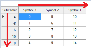
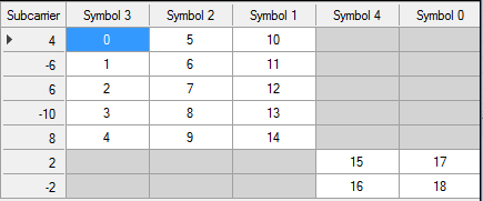
Select the resource mapping order for both symbol index and subcarrier index. Below are a few examples.
For the case of not using group ID:
First to Last: The Payload/IQ values will map to the symbol/subcarrier index based on the order of input string.
Symbol Index: 3, 2, 1
Subcarrier Index: 4, -6, 6, -10, 8
IQ Values: 0, 1, 2, 3, 4, … 14
You can see the IQ values are mapped based on the order of input string.
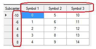
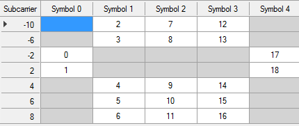
Low to High: The Payload/IQ values will map to the symbol/subcarrier index based on the sorted order of input string. You can see in the picture below that the symbol index and subcarrier index are sorted from low to high.
For the case of using group ID:
First to Last: Based on the previous example, the group 2 is added. In First to Last mapping, these two groups are independent. The IQ values are mapping to group1, then group2, and follow the First to Last rule in the same way as the not using group ID case.
Symbol Index: {1|3,2,1}, {2|4,0}
Subcarrier Index: {1|4,-6,6,-10,8}, {2|2,-2}
IQ Values: 0, 1, 2, 3, 4, … 18
Low to High: In this case, both symbol index and subcarrier index are sorted across all groups, and the IQ values are mapped from low to high across all the groups. Skip the subcarriers which are not defined in current group.
|
SCPI Command |
[:SOURce]:RADio:CMODulation:WAVeform[:ARB]:OFDM:RCONfig<channel>:RMORder FTLast|LTHigh [:SOURce]:RADio:CMODulation:WAVeform[:ARB]:OFDM:RCONfig<channel>:RMORder? |
|
SCPI Example |
|
|
Couplings |
|
|
Preset |
FTLast |
|
State Saved |
Yes |
|
Initial S/W Revision |
A.20.01 |
Choices: Preamble | Pilot | Data
Default: Data
Select the mapping type of the resource block.
Preamble: This type of resource block usually appears at the beginning of a frame and contains a fixed IQ pattern for the synchronization purpose. This type has the highest priority in resource mapping, meaning that it will override other types when there is a resource allocation conflict.
Pilot: This type of resource block usually appears at specific OFDM symbols and subcarriers and contains a sequence of modulated symbols for channel estimation purpose. This type has a higher priority in resource mapping than Data, meaning that it will override Data block when there is a resource allocation conflict.
Data: This type of resource block usually occupies the rest resources excluding Preamble and Pilot and is used for PHY payload data transmission with different modulation schemes. This type has the lowest priority in resource mapping.
|
SCPI Command |
[:SOURce]:RADio:CMODulation:WAVeform[:ARB]:OFDM:RCONfig<channel>:RMAPping DATA|PILOt|PREAmble [:SOURce]:RADio:CMODulation:WAVeform[:ARB]:OFDM:RCONfig<channel>:RMAPping? |
|
SCPI Example |
|
|
Couplings |
|
|
Preset |
DATA |
|
State Saved |
Yes |
|
Initial S/W Revision |
A.20.01 |
Range: 0.1 to 10
Default: 1.00
Set the amplitude boost level for the modulated symbols in the resource block, in linear value. e.g. original symbol 1+i with boost level 2.5 will be 2.5+2.5i.
|
SCPI Command |
[:SOURce]:RADio:CMODulation:WAVeform[:ARB]:OFDM:RCONfig<channel>:BLEVel <real> [:SOURce]:RADio:CMODulation:WAVeform[:ARB]:OFDM:RCONfig<channel>:BLEVel? |
|
SCPI Example |
|
|
Couplings |
|
|
Preset |
1 |
|
State Saved |
Yes |
|
Min |
|
|
Max |
|
|
Initial S/W Revision |
A.20.01 |
Choices: Payload Bit | IQ Values
Default: Payload Bit
Select the data mode for pilot. Pilot pattern can be defined in two ways:
You can input pilot IQ values directly.
You can specify the payload bits with a modulation scheme.
|
SCPI Command |
[:SOURce]:RADio:CMODulation:WAVeform[:ARB]:OFDM:RCONfig<channel>:PDMode PBIt|IVALues [:SOURce]:RADio:CMODulation:WAVeform[:ARB]:OFDM:RCONfig<channel>:PDMode? |
|
SCPI Example |
|
|
Couplings |
This setting is displayed only when Resource Mapping is set to Pilot. |
|
Preset |
PBIt |
|
State Saved |
Yes |
|
Initial S/W Revision |
A.20.01 |
Choices: BPSK | QPSK | 8PSK | 16QAM | 32QAM | 64QAM | 128QAM | 256QAM | 512QAM | 1024QAM | 2048 QAM | 4096QAM
Default: BPSK
Select the modulation scheme used for the resource block. The drop-down list contains all the constellations configured in Constellation Settings dialog, where symbol mapping for predefined constellations can be modified or new constellation can be created.
|
SCPI Command |
[:SOURce]:RADio:CMODulation:WAVeform[:ARB]:OFDM:RCONfig<channel>:RMODulation BPSK|QPSK|PSK8|QAM16|QAM32|QAM64|QAM128|QAM256|QAM512|QAM1024|QAM2048|QAM4096|QAM8192|QAM16384 [:SOURce]:RADio:CMODulation:WAVeform[:ARB]:OFDM:RCONfig<channel>:RMODulation? |
|
SCPI Example |
|
|
Couplings |
This setting is displayed only when Resource Mapping is set to Data. |
|
Preset |
BPSK |
|
State Saved |
Yes |
|
Initial S/W Revision |
A.20.01 |
Range: 0 to 360
Default: 0
Set an additional phase rotation, in degrees to the modulated symbols in the resource block.
|
SCPI Command |
[:SOURce]:RADio:CMODulation:WAVeform[:ARB]:OFDM:RCONfig<channel>:MPRotation <real> [:SOURce]:RADio:CMODulation:WAVeform[:ARB]:OFDM:RCONfig<channel>:MPRotation? |
|
SCPI Example |
|
|
Couplings |
This setting is displayed only when Resource Mapping is set to Data. |
|
Preset |
0 |
|
State Saved |
Yes |
|
Min |
|
|
Max |
|
|
Initial S/W Revision |
A.20.01 |
Choices: PN9 | PN15 | PN23 | Custom Bit Pattern | User File
Default: PN9
Click the > button displayed with this setting to open the Payload Data dialog where you can select the payload bits to be modulated in Pilot or Data resource block type. You can also load, save, and create custom bit patterns. The payload bit is mapped to resource element in subcarrier-first manner. It starts from the first valid symbol in Symbol Index, and go over each valid subcarrier in Subcarrier Index in sequential order. Then it moves to the next valid symbol, go over each valid subcarrier again, and so on.
PN Seed is in hexadecimal format and is applicable only to PN types (PN9, PN15, and PN23).
Offset is in decimal format and is applicable to all data types (including PN9, PN15, PN23, custom pattern, and user file).
|
SCPI Command |
[:SOURce]:RADio:CMODulation:WAVeform[:ARB]:OFDM:RCONfig<channel>:DATA:TYPE PN9|PN15|PN23|CUSTom|FILE [:SOURce]:RADio:CMODulation:WAVeform[:ARB]:OFDM:RCONfig<channel>:DATA:TYPE? |
|
SCPI Example |
|
|
Couplings |
|
|
Preset |
PN9 |
|
State Saved |
Yes |
|
Initial S/W Revision |
A.20.01 |
|
SCPI Command |
[:SOURce]:RADio:CMODulation:WAVeform[:ARB]:OFDM:RCONfig<channel>:DATA [:SOURce]:RADio:CMODulation:WAVeform[:ARB]:OFDM:RCONfig<channel>:DATA? |
|
SCPI Example |
|
|
Couplings |
|
|
Preset |
|
|
State Saved |
Yes |
|
Initial S/W Revision |
A.20.01 |
|
SCPI Command |
[:SOURce]:RADio:CMODulation:WAVeform[:ARB]:OFDM:RCONfig<channel>:DATA:FILE [:SOURce]:RADio:CMODulation:WAVeform[:ARB]:OFDM:RCONfig<channel>:DATA:FILE? |
|
SCPI Example |
|
|
Couplings |
|
|
Preset |
|
|
State Saved |
Yes |
|
Initial S/W Revision |
A.20.01 |
|
SCPI Command |
[:SOURce]:RADio:CMODulation:WAVeform[:ARB]:OFDM:RCONfig<channel>:DATA:PNSeed <integer> [:SOURce]:RADio:CMODulation:WAVeform[:ARB]:OFDM:RCONfig<channel>:DATA:PNSeed? |
|
SCPI Example |
|
|
Couplings |
|
|
Preset |
8388607 |
|
State Saved |
Yes |
|
Min |
0 |
|
Max |
8388607 |
|
Initial S/W Revision |
A.20.01 |
|
SCPI Command |
[:SOURce]:RADio:CMODulation:WAVeform[:ARB]:OFDM:RCONfig<channel>:DATA:OFFSet <integer> [:SOURce]:RADio:CMODulation:WAVeform[:ARB]:OFDM:RCONfig<channel>:DATA:OFFSet? |
|
SCPI Example |
|
|
Couplings |
|
|
Preset |
0 |
|
State Saved |
Yes |
|
Min |
0 |
|
Max |
|
|
Initial S/W Revision |
A.20.01 |
Choices: On | Off
Default: Off
Enable or disable the DFT spread before IFFT.
When enabled, a DFT will be performed to modulated symbols and then map the output to allocated resource elements. This processing is represented by the dotted part below:
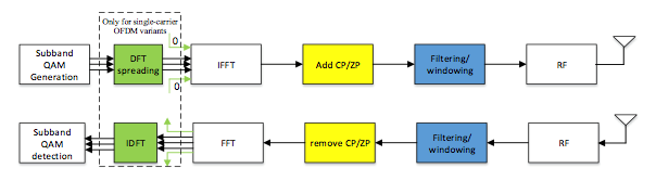
This parameter is required for signals with SC-FDMA multiple access, such as an LTE uplink signal. The DFT size will be the number of resource elements defined in the resource block.
|
SCPI Command |
[:SOURce]:RADio:CMODulation:WAVeform[:ARB]:OFDM:RCONfig<channel>:DSPRead ON|OFF|1|0 [:SOURce]:RADio:CMODulation:WAVeform[:ARB]:OFDM:RCONfig<channel>:DSPRead? |
|
SCPI Example |
|
|
Couplings |
|
|
Preset |
OFF |
|
State Saved |
Yes |
|
Initial S/W Revision |
A.20.01 |
Click the > button displayed with this setting to open an editor to configure IQ values transmitted in Preamble resource block type.
Zadoff-Chu
Clicking the Preset drop-down menu in the editor allows you to select Zadoff-Chu, which opens an editor for configuring a Zadoff-Chu sequence onto the subcarriers. This selection is available for LTE P-SS in the downlink and DMRS in the uplink.
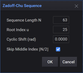
The root sequence is generated with:

Sequence Length (L): Number of values in the sequence.
Root Index (q): The root index of the sequence.
Skip Middle Index: When checked, the value with the middle index (L/2) will be removed from the sequence. For example, P-SS in LTE downlink skips the DC subcarrier.
Cyclic Shift (a): The shifted sequence is generated with a cyclic shift (in unit of π) to the root sequence with:

|
SCPI Command |
[:SOURce]:RADio:CMODulation:WAVeform[:ARB]:OFDM:RCONfig<channel>:IVALues [:SOURce]:RADio:CMODulation:WAVeform[:ARB]:OFDM:RCONfig<channel>:IVALues? |
|
SCPI Example |
|
|
Couplings |
This setting is displayed only when you set Resource Mapping to Preamble or Pilot and Continuous Payload to OFF. |
|
Preset |
0,0 |
|
State Saved |
Yes |
|
Initial S/W Revision |
A.20.01 |
Click the > button displayed with this setting to open an editor to configure IQ values for multi-carriers.
See also Continuous Payload.
|
SCPI Command |
[:SOURce]:RADio:CMODulation:WAVeform[:ARB]:OFDM:RCONfig<channel>:IVALues:MCARrier [:SOURce]:RADio:CMODulation:WAVeform[:ARB]:OFDM:RCONfig<channel>:IVALues:MCARrier? |
|
SCPI Example |
|
|
Couplings |
This setting is displayed only when you set Resource Mapping to Preamble and Continuous Payload to ON. |
|
Preset |
0,0 |
|
State Saved |
Yes |
|
Initial S/W Revision |
A.20.01 |
Range: 1 to 8
Default: 1
Read-only
Gets the number of antennas included in the waveform.
|
SCPI Command |
[:SOURce]:RADio:CMODulation:WAVeform[:ARB]:OFDM:RCONfig<channel>:ANTennas:COUNt <integer> [:SOURce]:RADio:CMODulation:WAVeform[:ARB]:OFDM:RCONfig<channel>:ANTennas:COUNt? |
|
SCPI Example |
|
|
Couplings |
|
|
Preset |
0 |
|
State Saved |
Yes |
|
Min |
|
|
Max |
|
|
Initial S/W Revision |
A.20.01 |
Default: The default value is 0, which is corresponding to Antenna0.
Set the Stream(s) Generated used for the transmission of this channel. Multiple values inputs are allowed, such as 0,1,2,3, or 0:3.
|
SCPI Command |
[:SOURce]:RADio:CMODulation:WAVeform[:ARB]:OFDM:RCONfig<channel>:STReams:GENerated [:SOURce]:RADio:CMODulation:WAVeform[:ARB]:OFDM:RCONfig<channel>:STReams:GENerated? |
|
SCPI Example |
|
|
Couplings |
The Number of Antennas is automatically coupled with the number of Stream(s) Generated. |
|
Preset |
|
|
State Saved |
Yes |
|
Initial S/W Revision |
A.20.01 |